Configuring devices#
Adding a device#
To add a device to your VR system description, simply go to the Devices
tab, and click the '+' button to display the Add Device window:
Devices#
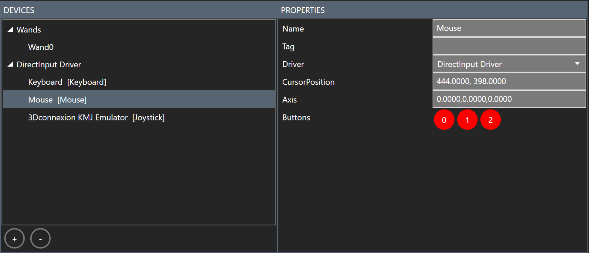
Keyboard, mouse, joysticks#
Keyboard, mouse and all available joysticks are automatically added by the DirectInput driver when MiddleVR is initialized:
A.R.T. DTrack#
The DTrack driver lets MiddleVR receive positions and orientations of A.R.T. Flysticks, body and finger targets, and also values of Flystick joysticks and Flystick button states.
The settings "Right", "Front" and "Up" let you provide the coordinate system that your A.R.T system is calibrated with (see "Adjusting the coordinate system").
In order to work, the DTrack driver must listen on a local port (default 5000) and create a set of MiddleVR trackers (default to 1).
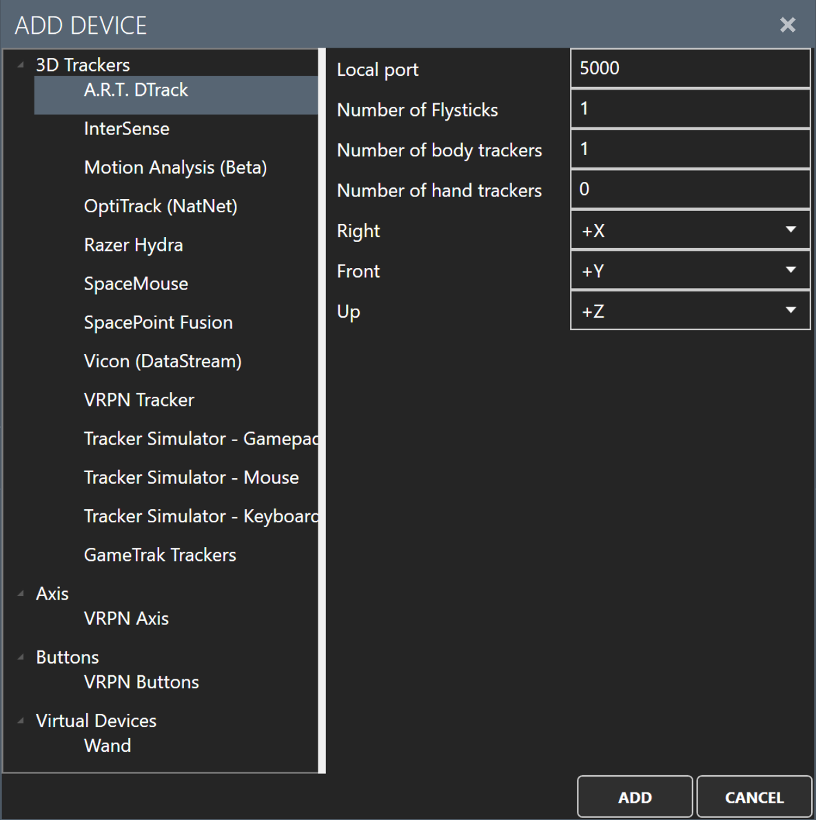
The driver will try to listen on the local port immediately after its addition. It is important that you check it did not display the following error message: "[X] DTrack driver: Init error. Check that the local port '5000' is available.". As it is suggested, this port (here, 5000) is already in use by an application, so you should use another port number.
![]()
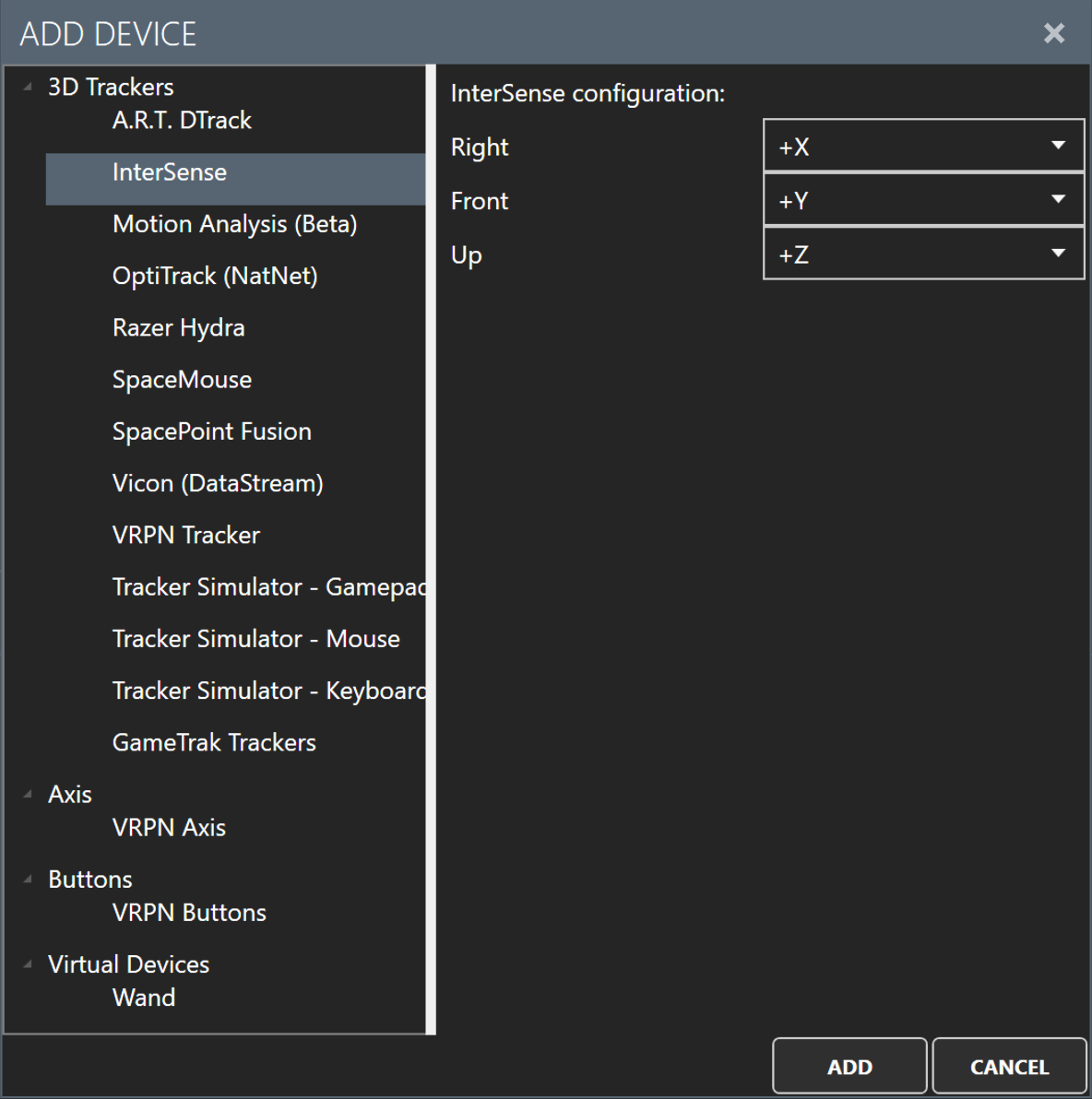
InterSense#
The InterSense driver provides position and rotation of tracking stations. This information is determined by the accelerometers and gyros of those tracking stations and is being corrected by fusing the output of the inertial sensors with range measurements obtained from ultrasonic components.
A "Device" is an InterSense Processor Unit like the IS-900.
A "Tracker" is an InterSense tracked device (aka InterSense station): it gives positions and orientations from the coordinate system that is provided through the parameters named "Right", "Front" and "Up" (see "Adjusting the coordinate system").
Some InterSense Stations are wands (tracker, joystick and buttons) or styluses (buttons). InterSense Stations are plugged to InterSense Processor Units.
For each InterSense Station, MiddleVR provides:
- a virtual tracker with positions and orientations.
- two axis for joysticks inputs.
- buttons states.
Axis and buttons are updated only when wand or stylus are connected to an InterSense Processor Unit.
Note: the InterSense Driver will always assume that there are as many connected InterSense stations as the maximum number of addressable stations.
![]()
Please have a look to the InterSense documentation for hardware configuration. It is suggested that you put the "isports.ini" file (if you need to use it) in a directory specified by the "ISPORTS_INI_DIR" environment variable. This folder should not reside in the MiddleVR system folders in order to keep a clean installation.
The content of the "isports.ini" file varies according to your hardware setup:
-
Example with a RS-232 connection:
Port1 = COM1:115200
The baud rate is optional and defaults to the maximum performance: 115200. You might lower the value if you use a long serial cable. -
Example with a remote computer (via TCP):
Port1 = ip:port
The IP "port" will probably equal to the default value: 5005.
If you encounter difficulties to use a RS-232 connection, we recommend that you check the version of the firmware and upgrade it before trying again.
NaturalPoint OptiTrack Trackers (NatNet SDK)#
OptiTrack trackers are infrared trackers that will report orientation and position. The system is intended for body motion capture with high precision and low latency.
The configuration requires an IP address of the computer that is running a NaturalPoint tracking software (e.g. Motive).
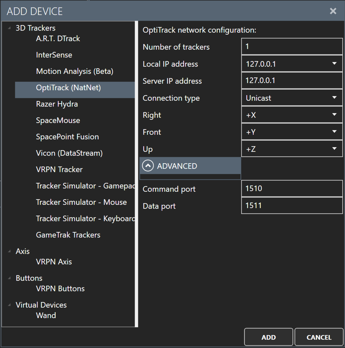
-
Number of trackers : The maximum number of trackers to read values from.
-
Local IP Address : Your IP address. It might be "127.0.0.1" if you run the software Motive on this computer. Otherwise, be sure that you use an IP address for the same network than the server running Motive.
-
Server IP Address : IP address of the computer running the software Motive.
-
Connection type : Select whether unicast or multicast transmission should be used. If the server delivers data to one computer only, both options should lead to the same performance. Note that this setting must match what is selected in the server to enable communication.
-
Right/Front/Up : Let you provide the coordinate system that your OptiTrack system is calibrated with (see "Adjusting the coordinate system").
-
Command port (Advanced) : Port to send/receive commands to/from the server. By default, the server uses the port 1510 in UDP to send and receive. Your firewall must allow the communication.
-
Data port (Advanced) : Port to receive data from the server. By default, the server uses the port 1511 in UDP to send data. Meanwhile, this computer (i.e. the local machine) also uses the port 1511 in UDP to receive data from the server. Your firewall must allow the communication.
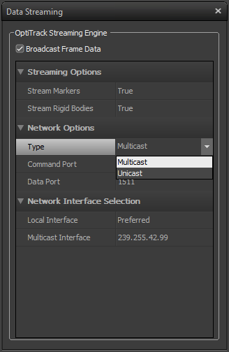
If you encounter problems to connect to a server, or receive data please check out the following points:
- the server and your machine use the same connection type (i.e. unicast/multicast). Prefer unicast to ease the configuration.
- command and data port are correct.
- communication is not blocked by a firewall.
- the setting 'Broadcast Frame Data' in the server is checked.
- the local interface is not set to "local loopback" but to the IP of the machine if Motive and MiddleVR-Config (or your simulation) do not run on the same computer.
![]()
Razer Hydra trackers#
The Razer Hydra has two magnetic trackers as well as a joystick and several buttons on each trackers.
SpaceMouse#
A SpaceMouse is a hardware device that lets a user translate and rotate objects in 3D. As the name suggests, it also provides buttons to trigger actions.
There is no configuration required for this device.
The SpaceMouse tracker is a tracker that can be translated and rotated in 3D by a SpaceMouse device. The configuration fields are described below.
![]()
-
Tracker translation speed : A factor to be applied on the translation that comes from the SpaceMouse. This factor depends on time, hence it is expressed as linear-movement unity per second.
The SpaceMouse sends arbitrary quantities so it is
impossible to talk about meter per second (m/s) for
example. However, the SpaceMouse control panel can
also be tweaked to increase or decrease the
translations that the SpaceMouse sends to software
including MiddleVR, see its settings. -
Tracker rotation speed : A factor to be applied on the rotation that comes from the SpaceMouse. This factor is similar to the
translation speed but is expressed as an angular
velocity, in degrees. The SpaceMouse control panel can also be tweaked to increase or decrease the angle values it sends to software including MiddleVR, see its settings. -
Tracker movements in local space : When checked, tracker movements are expressed in the local space of the tracker.
Assuming a 3D space with X to right, Y pointing forward and Z to the top, let's now consider that it is checked and that you rotated the tracker around the X axis by 45 degrees. If you then move the tracker forward, it will go along the Y axis that was rotated by 45 degrees. Said differently, the tracker will "climb".
If we now consider that we are working in global space, then the Y axis remains flat (i.e. aligned with the global Y axis of the world). Said differently, you are moving the rotated tracker along the flat Y axis and you look towards the top. In addition, rotations are relative to the world axis but around the object pivot.
Vicon Trackers (DataStream SDK)#
Vicon trackers are infrared trackers that will report orientation and position. The system is intended for body motion capture with high precision and low latency.
The configuration requires an IP address of the computer that is running a Vicon tracking software (e.g. Vicon Tracker).
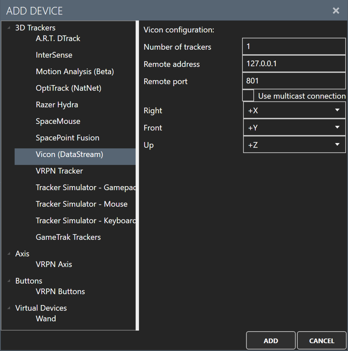
-
Number of trackers : The maximum number of trackers to read values from.
-
Remote Address : IP address of a computer running a Vicon's software to read data from.
-
Remote Port : Port to be used on the computer with a running Vicon's software.
-
Use multicast connection : Select whether unicast or multicast transmission should be used. If the server delivers data to one computer only, both options should lead to the same performance. Note that another connected client must have turned on before this type of connection.
-
Right/Front/Up : Let you provide the coordinate system that your Vicon system is calibrated with (see "Adjusting the coordinate system").
MiddleVR Trackers can only use sets of labeled Vicon's markers.
So how to get sets of labeled markers? Indeed, MiddleVR trackers directly match to what Vicon names Segments. A Segment is for example a tracked forearm and is always made up of markers. Thus sets of labeled markers are automatically obtained from Segments, or as Objects (which is the another name used by Vicon in its Tracker software to designate Segments).
![]()
![]()
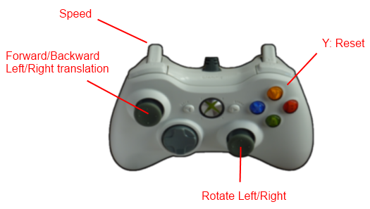
Tracker Simulator - Gamepad#
MiddleVR is able to simulate a 3D tracker with an official Microsoft XBOX 360 gamepad. This is useful if you don't have a real 3D tracker available, or simple if you want to navigate with a Gamepad.
For the moment only an official XBOX 360 gamepad will work.
Tracker Simulator - Mouse#
MiddleVR can simulate a 3D tracker with a three buttons mouse.
In Unity Editor and MiddleVR Config, you must press Shift to enable it.
- Press middle mouse button to move forward/backward and rotate (yaw).
- Pressing the Alt key will translate left/right, up/down.
- Pressing both left and right mouse button will reset the tracker.
Tracker Simulator - Keyboard#
MiddleVR can simulate a 3D tracker with key presses.
- Press Ctrl + X/Y/Z to translate.
- Press Ctrl + Alt + Y/P/R to rotate.
- Adding the Shift key will reverse translations and rotations.
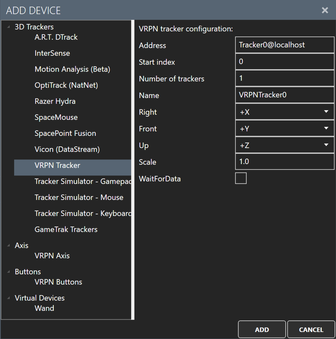
VRPN Tracker#
VRPN (Virtual Reality Peripheral Network) http://www.cs.unc.edu/Research/vrpn/ is an open-source project that handles lots of different VR devices. VRPN requires that you configure a server with the devices that you want to use.
Note: Where possible it is preferable to use native drivers rather than the VRPN client. This will give you more control and less latency
MiddleVR can handle VRPN trackers, axis and buttons. This section describes the configuration of trackers. For axis and buttons, see below.
Once the VRPN server is up and running, you must specify in MiddleVR the address and optionally the port of this server, the number of trackers that you want to use, and optionally modify the way axis are applied.
-
Address : Address of the VRPN server, plus the name of a particular device on this server. Examples: Tracker0@localhost, Tracker1@192.168.1.99, Kinect@LabPC.Moulinsart.fr. You can also specify the port of the server: Tracker0@localhost:3884, Tracker1@192.168.1.99:3886. The default VRPN port is 3883.
-
Index : A device, such as a Polhemus 3D tracker, can send data of multiple 3D trackers through one device. For example Tracker0@localhost can represent 10 different trackers, also named channels. Index specifies the starting index of the device.
-
Number of trackers : After specifying the starting index, you can also specify the number of trackers (devices) to use. For example, an index of 0 and a Number of trackers of 3 will result in the usage of channels 0,1,2. A starting index of 4 and a 2 trackers will result in the usage of trackers 3 and 4.
-
Name : Name prefix for each tracker.
-
Right/Front/Up : Axis coordinate system (see "Adjusting the coordinate system").
-
Scale : A factor to be applied on each tracker value. This value must be not null and positive. One can find it useful to adapt VRPN values with the dimensions of the current virtual world.
-
Wait for data : Should the driver wait until a new data arrives? This can be useful in case your tracker sends updates at the same refresh rate as your display. It means that for each frame you know you'll have a new update, and not miss an update.
Once the VRPN trackers are added, you will immediately be able to see if the data are streamed correctly:
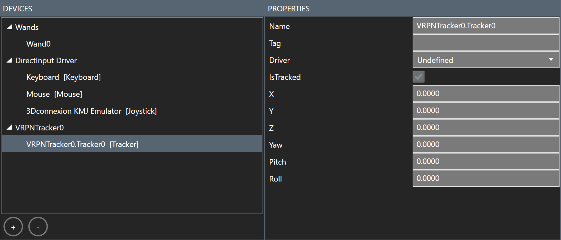
If the VRPN server is not reachable, you will probably see the following error in the log window:

For more information about troubleshooting VRPN, see Troubleshooting VRPN on the knowledge base.
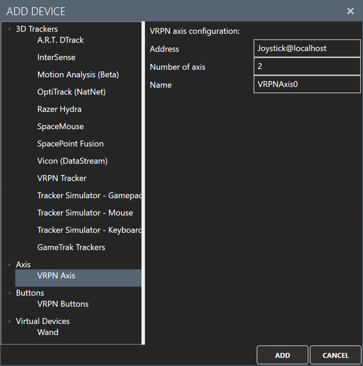
VRPN Axis#
VRPN Axis can represent joystick axis, sliders or other analog information.
-
Address : Address of the VRPN server, plus the name of a particular device on this server. Examples: Joystick@localhost, Mouse0@192.168.1.99, Sliders1@LabPC.Moulinsart.fr. You can also specify the port of the server: Joystick@localhost:3884, Mouse0@192.168.1.99:3886. The default VRPN port is 3883.
-
Number of axis :Number of axis on this device.
-
Name : MiddleVR device name.
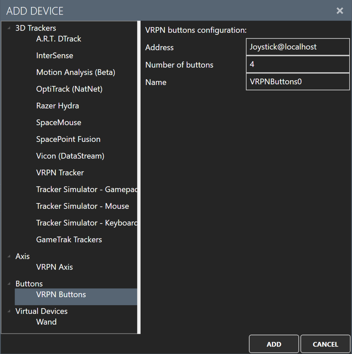
VRPN Buttons#
VRPN Buttons represent a button with a value of true or false.
-
Address : Address of the VRPN server, plus the name of a particular device on this server. Examples: Joystick@localhost, Mouse0@192.168.1.99, Sliders1@LabPC.Moulinsart.fr. You can also specify the port of the server: Joystick@localhost:3884, Mouse0@192.168.1.99:3886. The default VRPN port is 3883.
-
Number of buttons : Number of buttons on this device.
-
Name : MiddleVR device name.
Configuring the Wand#
As mentioned previously, the Wand is composed of three parts:
- a 3D tracker,
- a two-axis joystick,
- a set of buttons.
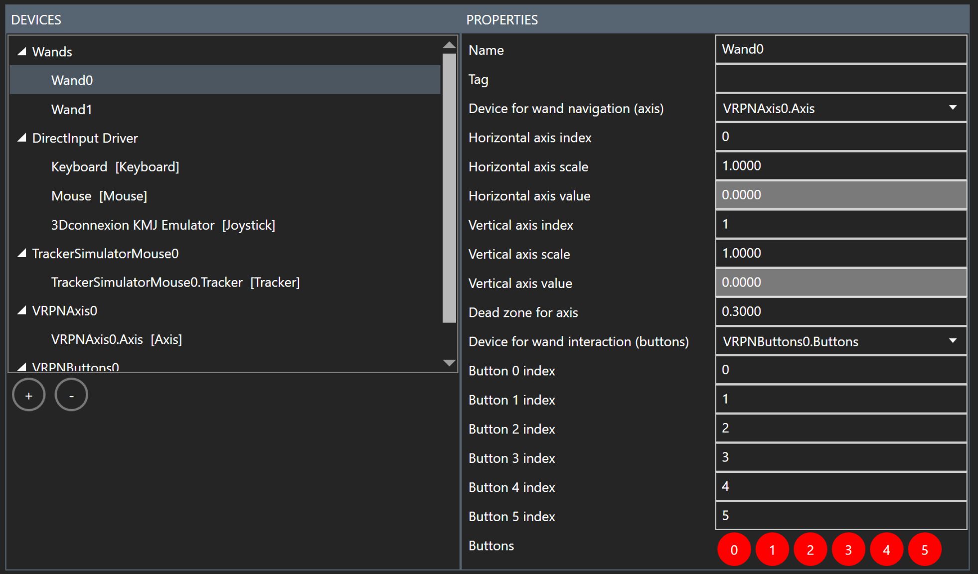
You have to manually add and configure the three devices that will make up the wand. In the screenshot above, we have added a VRPN Tracker, VRPN Axis for the joystick axis, and VRPN Buttons for the buttons.
You can also use a simple joystick for the axis and buttons. You can also use mouse buttons.
You then have to specify in the Wand section, which axis and buttons devices you want to use, and the ordering of the axis and buttons.
You also have to assign the tracker to the HandNode.
Finally you have to configure the usage of the Wand in Unity.
-
Device for wand navigation (axis) :The device that will be used to get the wand joystick axis values
-
Horizontal axis index : Index of the horizontal axis of the joystick
-
Horizontal axis scale : Scale factor that should be applied to the value of the horizontal axis
-
Horizontal axis value : Display value of the computed horizontal axis after scaling
-
Vertical axis index : Index of the vertical axis of the joystick
-
Vertical axis scale : Scale factor that should be applied to the value of the vertical axis
-
Vertical axis value : Display value of the computed vertical axis after scaling
-
Device for wand interaction (buttons) : The device that will be used to get the wand buttons states
-
Button 0 index : Index of the primary button
-
Button1 index : Index of the secondary button
Sometimes, only one wand is not enough. In these cases, you will need to add and configure additional wands to your configuration. This way, you will be able to retrieve the wand you want from the device manager and get it's tracker, axis and buttons data.